This is the second part of ST-Link reverse-engineering, where I cover dumping the firmware, extracting and reverse-engineering the bootloader, and finally, patching the bootloader in order to disable Level 1 protection.
Dumping the bootloader
Dumping the firmware was the easiest part. Once the bootloader passes control to our code, we initialize clocks and UART. After that we send two marker bytes to indicate beginning of the firmware and then simply read all the flash memory starting from the address 0x08000000 and send it over UART one byte at a time. Since I was too lazy to implement any flow control, I opted for modest 9600 baud and added a small delay after each byte transfer just to make sure that I don’t hit a buffer overrun on my UART-USB converter. TX pin on UART2 is PA2 (there are solder-bridges for RX and TX on Discovery boards).
1 | void main() { |
After I accidentally triggered mass-erase on my Nucleo board, I had only one board with ST-Link v2-1 left. I didn’t want to risk, so I tried dumping a Chinese ST-Link v2 clone first. Once the update process finished, the programmer immediately started to spit out it’s own flash contents over the serial interface.
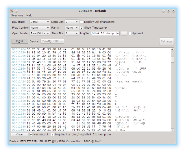
As I mentioned before, visualizing raw binary data is a very useful trick during analysis. Let’s see what the dump looks like.
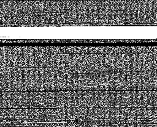
We clearly see the separation between the bootloader and user code. Most importantly, there is a small chunk of data near the end of the bootloader section (later I discovered these bytes are written by the bootloader at the end of the update process to indicate a valid firmware). We can also see that first two pages of memory in the user code section were erased and now contain our dumper code.
As I mentioned in Part 1, my attempt to access the microcontroller through a debugger resulted in flash mass-erase. According to the reference manual, it implies that Level 1 protection is activated: “Level 1 protection allows to recover a programmed part by erasing the entire Flash content. This is done by re-programming the RDP option byte from Level 1 to Level 0.” The programming manual tells us where the option bytes are located.

Before we move on to reverse-engineering the binary, let’s extract the bootloader section first, excluding the version bytes near the end:
1 | $ cat stlink_v2_dump.bin | head -c 15360 > ST-Link_bootloader.bin |
At this point, flashing bootloader onto an empty microcontroller will make the update utility think a blank ST-Link is connected. It will let you choose which firmware to flash, however the results will not be any different from what we achieved before by tricking the updater into flashing a different firmware.
Reverse-engineering
There are many disassemblers available for ARM out there. One of them even works. Unfortunately, IDA demo version does not support binary files. I tried using radare2, but after a while decided that I don’t have a spare lifetime to learn how to use all of it’s hot-keys and commands.
Eventually, I came across Hopper, which is a cross-platform disassembler. Demo version is limited to 30min sessions and does not allow saving projects or exporting files. That seemed good enough for me, so I gave it a try.
First things first, I searched for 0x1FFFF800 and sure enough - this constant was present.
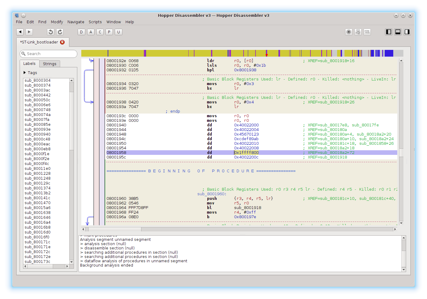
It is referenced only once (hitting X lists all the references). If we follow the reference, we end up in a subroutine that presumably sets up the option bytes. Hopper can also generate pseudo-code. It’s not that great with loops and conditionals, but comes in handy when analyzing arithmetic operations.
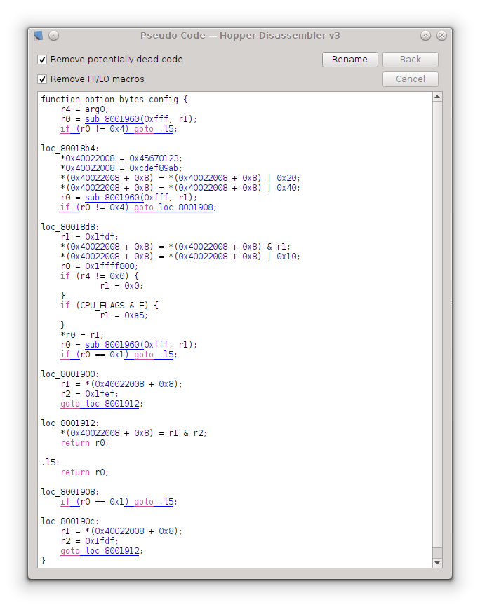
This function is called only once, and if we follow the reference we end up in a section with quite a few function calls. Control flow graph shows that we identified main program loop at 0x2198. I tried visiting all the functions and guessing what they do.
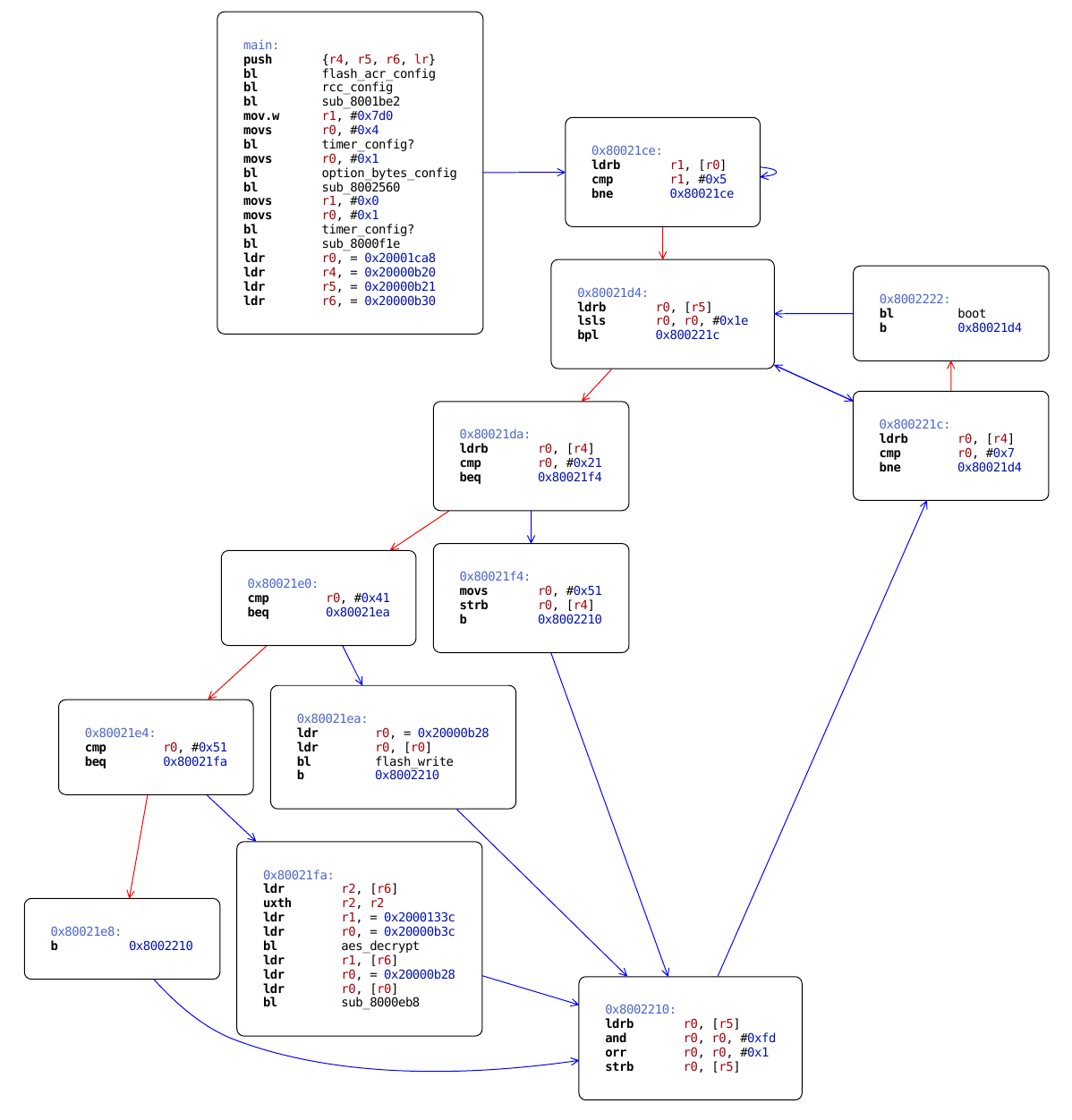
Disabling protection
We know that the function call to option_bytes_config is located at 0x21B2 in the binary dump. Let’s try to ‘nop’ it and see what we get. NOP is a pseudo-instruction on ARM cores, so we have to use something like ‘mov r8,r8’ to skip a cycle.
1 | $ echo "mov r8, r8" | arm-none-eabi-as -mthumb -march=armv7 && arm-none-eabi-objdump -d a.out |
Branch instruction occupies 4 bytes, which means we have to patch C0 46 C0 46 to ‘nop’ the function call.
Next we flash the patched bootloader and use the updater utility to upload ST-Link firmware. Now let’s try dumping the firmware with openocd to see if protection is still enabled.
1 | $ openocd -f interface/stlink-v2.cfg -c 'transport select hla_swd' \ |
And this is what we get:
1 | ... |
Success!
Conclusion
After I dumped the firmware from the ST-Link v2 clone I successfully repeated the same procedure for an ST-Link v2-1. I used the same approach for removing protection, although the main program loop was a bit trickier to find. Being able to use a debugger makes it significantly easier to study the functionality of the bootloader and main firmware.