This article will cover developing for STM8 series of microcontrolles completely from scratch, without using any vendor-supplied libraries.
Preface
STM8 is a cheap 8-bit microcontroller aimed towards low-cost mass-market devices. Initially I came across this part while searching for a simple microcontroller as a replacement for AVRs. Despite having various ARM Cortex-M0 devices available on the market for quite attractive prices, AVRs have one advantage - simplicity. Utilizing an ARM Cortex core to switch some lights on and off seems like an overkill. Some applications just don’t require that amount of flexibility and performance.
The main goal of this article is to demonstrate that ‘bare metal’ programming is not a difficult task and to give you an overview of STM8’s architecture and peripherals. Even though writing peripheral drivers from scratch might seem like reinventing the wheel, in many cases it is easier and faster to implement the functionality that you need for a specific task, instead of relying on vendor-supplied libraries that try to do everything at once (and fail).
Contents:
- The Hardware
- Setting up toolchain
- It’s all just memory..
- First program
- Peripheral drivers
– UART
– SPI
– I2C
– ADC
– Timers and interrupts - Putting it all together
- Conclusion
The Hardware
There is a number of ways to start working with STM8. The easiest one is to get a Discovery board, although I wouldn’t recommend it, since STM8 Discovery boards aren’t that good and the on-board ST-Link v1 firmware just sucks.
Instead, I’ll opt for the minimalist approach. All you need is an ST-Link v2, STM8S003F3 and a breakout board. STM8S003F3 comes in a handy TSSOP20 package which is very easy to solder.
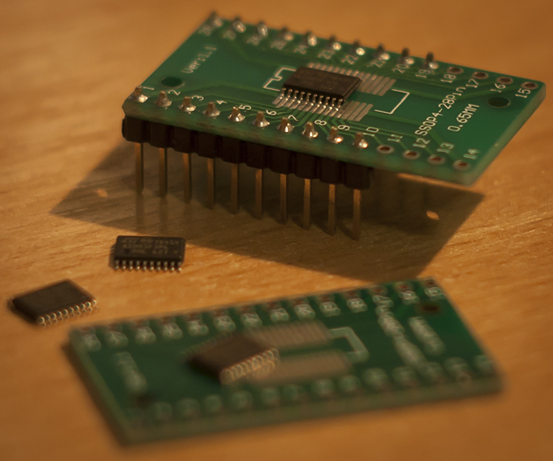
Note: a 1uF capacitor on VCAP pin is required for the processor to operate.
Setting up toolchain
The biggest downside is that STM8 processors are not supported by GCC. There are 3 commercial compilers available for these processors: Raisonance, Cosmic and IAR. Some of these compilers have free versions with code size limit, but none of them are available for linux. Luckily, SDCC supports STM8 and that’s what we’re going to use. SDCC is being actively developed, so I suggest trying the latest snapshot build instead of the stable version. To program the microcontroller we’ll be using stm8flash. The first step is to download all the necessary tools:
Extract SDCC under ~/local/sdcc. Now extract stm8flash, build it with make and copy stm8flash binary to ~/local/sdcc/bin. I prefer to keep flasher with compiler for convenience. Next, add the following line to your .bashrc file (replacing username with your user name):
1 | export PATH=$PATH:/home/username/local/sdcc |
If everything was done properly, you should be able to run sdcc --version. The last remaining thing is to write udev rule for ST-Link programmer. Create a file /etc/udev/rules.d/99-stlink.rules:
1 | # ST-Link v1/v2 |
Finally, run udevadm control --reload-rules && udevadm trigger as root. Now we’re all set and ready to start.
It’s all just memory..
Before we begin, let’s take a simple example of accessing port register on ATmega and see what’s going on under the hood:
1 | /* Port access operation */ |
Typecasting integer to a pointer is a valid operation in C. If you don’t quite understand what is going on with pointer arithmetics then here’s another example for you:
1 | uint8_t a = 0xDE; // a contains 0xDE |
The only difference is that in the first example we know exactly which address in memory we are going to use. It’s important that you understand what’s going on here, since we’re going to use this mechanism for accessing hardware registers later on.
First program
These are the two most important documents: datasheet and reference manual. We’ll use the datasheet for the pinout and register map. Everything else is present in the reference manual: peripheral operation, register description, etc. Let’s begin by opening the GPIO section of the reference manual and taking a closer look at PORTD registers.

These registers are pretty much self-explanatory but just in case, here’s a brief overview: DDR is the direction register, which configures a pin as either an input or an output. After we configured DDR we can use ODR for writing or IDR for reading pin state. Control registers CR1 and CR2 are used for configuring internal pull-ups, output speed and selecting between push-pull or pseudo open-drain.
First, let’s define a macro that we’ll use later on for register definitions. Base address for all the hardware registers is 0x5000 so we can hardcode that into our macro.
1 |
Now let’s try blinking an LED. For this task we need to define ODR, DDR and CR1 registers for PORTD. We also need a delay function.
1 |
|
Save this in main.c and compile by running the following command:
1 | sdcc -lstm8 -mstm8 --out-fmt-ihx --std-sdcc11 main.c |
Now attach st-link and flash the microcontroller.
1 | stm8flash -c stlinkv2 -p stm8s003f3 -w main.ihx |
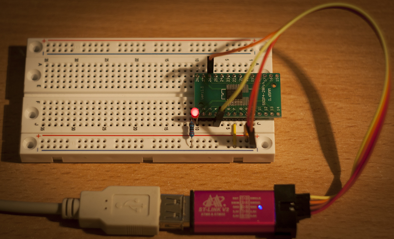
Congratulations! We’ve just written our first program from scratch.
Note: some of the STM8 pins are labeled with (T) in the datasheet. These pins are ‘true’ open-drain and can only pull to ground. You should be extra careful when working with open-drain pins, since there are no protection diodes. I managed to accidentally blow PB5 by using it as a normal GPIO, which took me hours to figure out when my I2C code wasn’t working. One way of checking whether the pin is dead or not is by setting the multimeter in diode mode and measuring the voltage drop between the pin and ground - it should be roughly 0.7V in one direction.
Peripheral drivers
UART
After toggling some IO pins the first thing that you should get up and running on a new platform is UART. It makes debugging much easier. As always, we begin with register definitions.
1 | /* UART */ |
Usually, in order to initialize UART one has to calculate baud and write the resulting value into the corresponding HIGH and LOW registers. Let’s see how this is done in STM8.
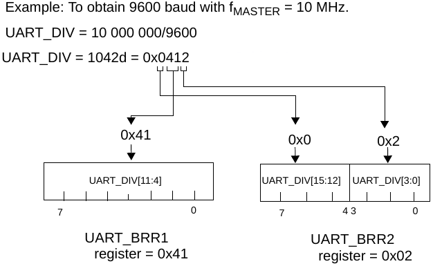
So.. you get a 16-bit value and you write the first nibble [15:12] into BRR2[7:4], then you write bits [11:4] into BRR1 and finally you write the remaining bits [3:0] into BRR2[3:0]. Seriously, what were they thinking? Why couldn’t ST just implement BRR_HIGH and BRR_LOW for the sake of it? All this bit-fiddling just seems unnecessarily complicated.
Anyway, let’s move on to initialization. We’ll stick with the default 8 data bits, 1 stop bit and no parity. Since our master clock is 2MHz, for baud = 9600 we have UART_DIV = 2000000/9600 = 208 (0xD0). According to the bizarre diagram above, we end up with BRR1 = 0x0D and BRR2 = 0x00. One thing to keep in mind is that BRR2 register must be written before BRR1. Finally, we turn on receiver and transmitter in Control Register 2. Read and write functions are pretty straight-forward: you read/write the Data Register and wait until the appropriate bit in Status Register is set.
1 | /* |
Redirecting stdout is easy with SDCC.
1 | int putchar(int c) { |
Now we’re all set and we can use printf() for debugging.
SPI
Next, we implement SPI master. SPI is quite an easy peripheral and is usually implemented as a simple shift-register in hardware. We need to define only 4 registers to start working with SPI.
1 | /* SPI */ |
Let’s implement initialization and read/write functions. Reading from SPI is achieved by writing a dummy byte, so we’ll hardcode SPI_write(0xFF) inside our SPI_read() function. Chip select pin will be managed in software.
1 | /* |
To test our implementation I’ve written a simple loop that transmits some data.
1 | void main() { |
Let’s hook up the logic analyzer and have a look.

Hmm.. something is wrong. It seems that we release chip select too early and the last byte will not be received by a slave device. This can only occur if the SPI peripheral didn’t have enough time to finish transmitting before we released CS pin.
That wasn’t supposed to happen - we are polling for TXE bit, aren’t we? Well, the problem is that TXE only indicates that Tx buffer is empty. It doesn’t tell us that all the bits were shifted out by the shift register. So in order to properly end the transmission we have to check for BSY flag, which tells us whether or not SPI has finished an operation. Let’s modify our chip_deselect() function to take that into account.
1 | void chip_deselect() { |
Final output.

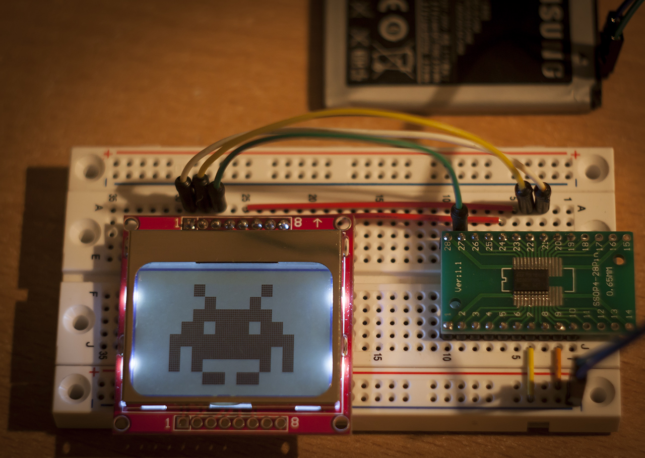
Our final test is the good old “Nokia 5110” LCD. Complete source is on github.
I2C
Now let’s get onto something more serious. I2C usually requires a bit more work to get it up and running comparing to SPI and UART. I2C has a lot of associated registers, so I will no longer list them from this point. You can find a header with register definitions here.
Let’s take a look at what the reference manual says about receive and transmit operations.
That does seem quite complicated: a lot of events are generated during communication. However, we don’t have to explicitly take care of every single event in order to have a working communication - some of the events are automatically cleared by hardware and some may just be ignored and left unattended. We’ll go with the easiest implementation.
We start by implementing initialization and IO functions. We also need dedicated functions to generate start and stop conditions.
1 | /* |
According to the reference manual, writing slave address is a special case so we can’t simply use i2c_write() to do that. We need a dedicated function for this purpose.
1 | void i2c_write_addr(uint8_t addr) { |
Reference manual says we are supposed to to handle EV6 event after writing slave address: “EV6: ADDR=1, cleared by reading SR1 register followed by reading SR3”. After polling for ADDR bit we simply read SR3 register. I’m not sure why this is required, probably to check for BUS_BUSY, but that seemed a bit pointless so we cheated a little.
Now, let’s test our library with an HMC5883L magnetometer. First we define R/W flags and some magnetometer related stuff:
1 |
We’ll implement a simple function that reads the device Id and sends it over UART.
1 | void hmc5883_get_id(uint8_t *id) { |
Output:
1 | Device ID: H43 |
All seems to work fine, but let’s take a look at the logic analyzer just to make sure.

Hmm.. we do receive correct bytes, but what’s the deal with that 0xFF received right after the NACK? It seems that something is wrong with our code. Time to RTFM.
The Proper Way
So the first problem is how we generate STOP condition. According to the documentation, we are supposed to generate STOP before reading the last byte. I changed the code but it didn’t fix the problem. The real problem was that I was porting the magnetometer driver which I wrote for a different microcontroller, so I expected the I2C peripheral to work in a certain way. Well, I was wrong.
The i2c_read() function is supposed to receive only 1 byte of data. It turns out there are 3 different scenarios for N=1, N=2 and N>2, where N is the number of received bytes. We can’t simply use the function for N=1 to read more than a single byte. That means we need separate functions to handle each case! I wonder how many logic gates were dedicated to implement I2C peripheral on this MCU… (Note: I2C implementation on STM32F1xx series is actually identical to STM8.)
Looking at the reference manual I figured that we could possibly combine N=2 and N>2 cases and handle them with a single function. Below are proper implementations of I2C receive functions.
1 | uint8_t i2c_read() { |
Now let’s update our code for reading device Id.
1 | void hmc5883_get_id(uint8_t *id) { |
Note that our i2c_read_buf() function generates STOP so we no longer have to call i2c_stop() manually. Let’s take a look at the logic analyzer now.

Great, no 0xFF at the end! Now we’re ready to move onto something different.
ADC
Nothing exciting about the ADC on STM8: 10-bit resolution, single and continuous conversion modes, configurable prescaler.. all the usual boring stuff. There is also a data buffer that can hold a number of ADC samples, which is rather convenient.
The default printf() implementation provided by SDCC does not support floats. To enable floating point output, printf_large.c needs to be recompiled with -DUSE_FLOATS=1 option. For this example we are going to cheat and print the results in millivolts instead. Without further ado, let’s write some code for single ADC conversion.
1 |
|
Pretty straight forward. Note that EOC flag has to be manually cleared by software.
A few things that should be taken into account when working with ADC:
- The order in which
DRLandDRHregisters are accessed depends on data alignment. - ADC has no internal voltage reference. STM8S003 does not have an external Vref pin, so it is tied to Vcc internally, which means that your supply voltage has to be spot-on for any serious measurements.
- Data buffer registers have no internal locking. ST provides an assembly snippet in the datasheet for reading buffer registers.
Timers and interrupts
You can’t get far without using timers and interrupts, which is what this last section will cover. STM8S003 has 16-bit ‘advanced control’ as well as 8-bit general-purpose timers. TIM1 is a really complicated peripheral with 32 dedicated registers, and covering it’s functionality would probably require a few extra articles. For this article, we’ll use TIM4 which is good enough for basic applications.
There isn’t much to tweak inside TIM4: it contains an 8-bit auto-reload up counter, 3-bit prescaler and an option to generate interrupt on counter overflow.
The prescaler divides counter clock frequency by a power of 2 from 1 to 128 depending on PSCR registers:
In this example we are going to toggle a pin each time the counter matches value in the ARR register. The frequency of the waveform generated by our IO pin is calculated as follows:
To achieve a frequency of 100Hz ARR has to be set to 77, given that our clock frequency is 2MHz. We need to enable Update Interrupt for TIM4, but before that interrupts must be enabled globally by executing rim instruction.
1 | int main() { |
Now, when I said that we’re going to implement everything from scratch, I wasn’t completely honest. We’re still using some start-up code which initializes the stack and interrupt vector table. If you look at the listing you can see that SDCC has generated the interrupt table for us:
1 | 000000 82v00u00u00 37 int s_GSINIT ;reset |
Registering an interrupt handler is easy with SDCC: there is a special attribute _interrupt() which takes interrupt number as a parameter. Section 7 (‘Interrupt vector mapping’) of the datasheet describes which IRQ number corresponds to which peripheral. For TIM4 it is 23. Our interrupt handler will look like this:
1 |
|
Putting it all together
We have enough building blocks - now it’s time to put them together into some ‘real-world’ application. For this demo I picked up MMA8452 3-axis I2C accelerometer and a standard HD44780 1602 LCD, which is extremely popular among electronics enthusiasts for some reason.
The demo application will calculate inclination angle based on accelerometer readings and output it to the LCD. Calculating inclination angle will require some trigonometry and floating point arithmetic, which will consume a good amount of resources. Despite the floating point operations being quite slow, STM8 managed this task decently.
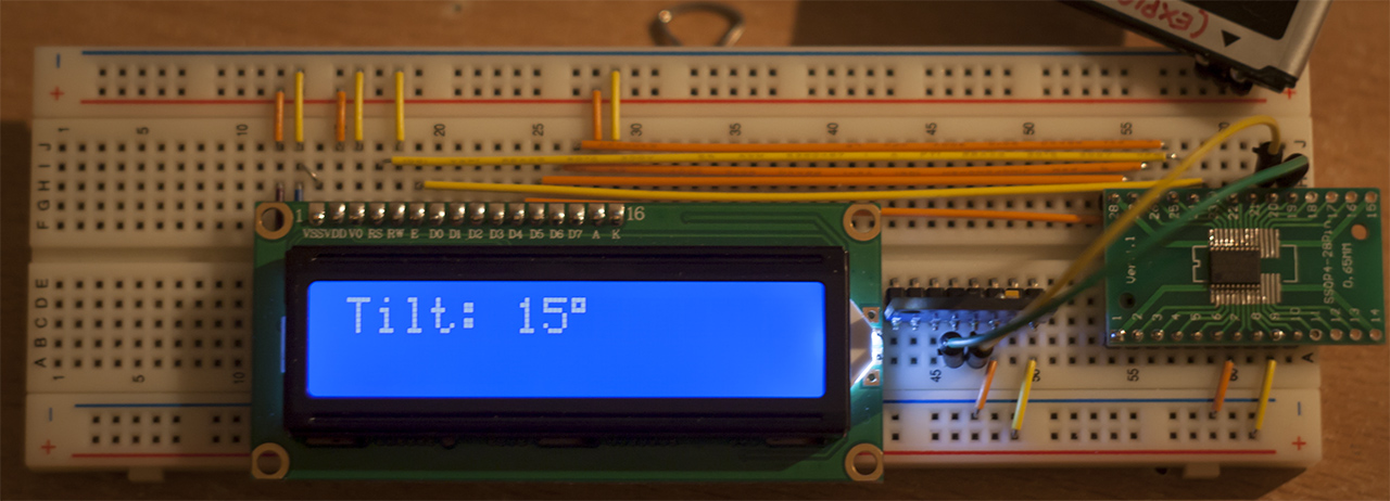
You might have noticed the lack of contrast adjustment potentiometer. The LCD module that I’m using is rated for 5V, however my setup uses 3.3V supply. I couldn’t be bothered with a separate supply for the display, so I cheated: the LCD is initialized in 1-line mode, which results in 1/8 duty cycle, and Vo pin is tied to ground.
Conclusion
STM8 is nice and cheap, but it is really hard to justify using this microcontroller, especially given the fact that price difference between STM8 and low-end Cortex-M0 devices like STM32F03 is negligible. The biggest downside for me was lack of GCC support. Despite SDCC being a reasonably good compiler, it does not fully support C99 and C11 standards, which means that I have to refactor most of my existing code to make it compatible. Code optimization isn’t great either, which is a shame, since most STM8 microcontrollers don’t have a lot of flash to spare.
As always, code is available on github.