This is the first part of ST-Link reverse-engineering, where I cover analyzing and decompiling the updater utility, decrypting and encrypting firmware binaries and running custom code on ST-Link v2/2-1 programmer.
Preface
ST-Link 2 is a neat programmer. It can program, debug and even supports SWO Trace. The more I use it, the more I seem to forget about this abomination. Recently, I came across a Nucleo board with an ST-Link v2-1, which in addition to all the regular features acts as a virtual COM port (VCP) and supports drag-n-drop upload. Sweet! Although I wasn’t very excited about the drag-n-drop thing, having UART for debugging on the same board comes in real handy. After studying the schematics I realized that the programmer is pretty much identical to a regular ST-Link v2 in terms of hardware. The only big difference is that v2-1 uses an MCU with 128k of flash versus 64k on v2 programmer. That made me think if there are any ways of getting UART on a ‘regular’ ST-Link. And so it began..
Research
EEVBlog forum user eliocor was kind enough to help and did a lot of research on the topic. He pointed me towards this discussion on the ST forums. According to the ST employee, there are 4 versions of ST-Link 2: ST-Link/v2, ST-Link/v2-A, ST-Link/v2-B and ST-Link/v2-1. Presumably, A, B and 2-1 versions all have UART support and a different bootloader. ST-Link/v2-1 also uses a larger MCU. Looking at windows drivers reveals a number of different PID combinations.
1 | VID_0483&PID_3748 |
Initially, I tried connecting to the MCU with J-Link and see if we get anything useful. I launched J-Link Commander, typed ‘connect’ and was very surprised.
1 | Active read protected STM32 device detected. This could cause problems during flash download. |
MCU committed suicide. Flash was completely erased and I lost my ST-Link. Apparently, J-Link linux utility was ‘kind’ enough to remove option bytes without even asking the user.
Despite the fact that I lost my programmer, I still learned some useful information. Being able to unsecure the chip by erasing the flash contents suggests that Level 1 protection is active (more on that in Part 2).
Analyzing the updater
There is an article by Taylor Killian written in 2013, which covers extracting ST-Link firmware from the updater executable. At first I tried following the author’s approach and disassembling the windows executable. I searched for string references and soon found a part of code that decides which firmware to flash based on the ID of the programmer. It was implemented as a switch statement and the disassembly looked like a simple jump table. I fiddled around with various conditional jumps and was able to ‘help’ the program flash a different firmware into the programmer. After a few attempts I detached st-link from the virtual box and dmesg greeted me with the following:
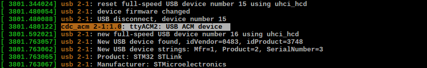
Hah, piece of cake! I tried opening /dev/ttyACM2 - no errors. Then I connected a dev-board and tried flashing it with my upgraded st-link. It didn’t work. The official flash utility failed with ‘ST-Link USB error’ and openocd refused to see the programmer at all. Moreover, when I unplugged and reattached st-link, CDC interface was gone. For some reason st-link refused to exit DFU mode.
I played around with windows update utility but quickly got bored. Luckily, ST were kind enough to have a cross-platform updater written in java, so that we no longer have to fire up a virtual machine just to update the firmware.
Extracting STLinkUpgrade.jar reveals some interesting binaries. I tried to match them with corresponding labels from the updater:
- f1_x.bin: ST-Link v1 firmwares. Not interested.
- f2_1.bin: “STM32 only”. Appears to be for Discovery boards.
- f2_2.bin: “STM8 only”. Also not interested.
- f2_3.bin: “STM32+STM8”. Standalone programmer, also used in Chinese clones.
- f2_4.bin: “STM32+MSD+VCP”. This one is for ST-Link v2-1 found on Nucleo boards.
- f2_5.bin: “STM32+Audio”. No idea.
So the firmware with UART support is obviously f2_4, but there is a slight problem: ST-Link v2-1 on a Nucleo board features an STM32F103CBT6 microcontroller with 128k of flash, so it’s unlikely that we’ll ever manage to squeeze it into an F103C8. The firmware I’m most interested in is f2_5 (“STM32+Audio”) - I have no idea what “Audio” means, but we know that there are at least two versions of ST-Link with UART capability so, presumably, this firmware is for one of them.
The first obvious step was to rename these files inside the .jar archive and make the updater flash the firmware that we want. Unfortunately, the results were the same as with patching the windows executable.
The next step was to figure out what format these files have. When working with unknown data, it’s always a good idea to have a visual representation of some sort. Judging by the uniform distribution of data we can suspect some encryption or archiving involved.

Now, it’s no secret that these binaries are encrypted with AES-128 and the key is stored inside the executable in plain ASCII, which was covered in the article I mentioned earlier. However, since I was planning to use the application itself to perform encryption/decryption, this information was of little use to me. So without any further investigation I went on to decompiling the updater utility.
I used procyon decompiler, reconstructed function calls and after a while was able to decrypt the firmware binary. Encryption key was “worst HAL libraries” “best performance”. Finally, I’ve hacked everything into a command-line utility, which is able to encrypt and decrypt binary images (code is available on github).
Let’s take a look at the decrypted file and search for known Unicode strings.
1 | 0x00008ee0: 80 14 00 20 04 03 09 04 26 03 53 00 54 00 4d 00 ... ....&.S.T.M. |
Looks promissing, right? ;)
The next step was to change something in the decrypted firmware, encrypt it and send back to the device. It worked flawlessly. As a sanity check, I tried various combinations, including flashing a firmware consisting entirely of 0xFF bytes, just to make sure that the firmware is indeed accepted and written to the device.
At this point I was not interested in analyzing the firmware any further. I realized that the bootloader plays an important role, and I won’t be able to proceed without obtaining it.
Hello, world
Knowing how to encrypt the firmware, I could flash anything I want. However, I had no idea how the bootloader decides whether or not the firmware is OK before it passes control to it. Therefore, I needed to test if the code would actually get executed on the device.
I decided to write a ‘Hello world’ program that would blink an LED on PA5 (SWCLK on the SWD connector). The first thing to do was to alter the linker script and offset the ROM section by the size of the bootloader section.
1 | MEMORY |
The code is rather self-explanatory.
1 | void main() { |
After compiling the binary I used my utility to encrypt the binary.
1 | $ java -jar st_decrypt.jar -k "best performance" -i main.bin -o f2_3.bin --encrypt |
Next, we replace the original f2_3.bin with our own, compress the jar archive and update the firmware on the st-link. For this test I used my F4 Discovery board. The update process finishes with an error saying that it can’t exit DFU mode. Let’s take a look at the board now.

It was the first time I was excited about a blinking LED on a development board ;) Once you unplug the power, st-link would start in DFU mode again (as it normally does). Each st-link related command like writing to flash or reading target voltage would first ask the st-link to exit DFU mode and start executing main firmware code.
Now I have a way of executing my own code on the programmer. The next obvious step is to retrieve the bootloader, which I’ll cover in Part 2.